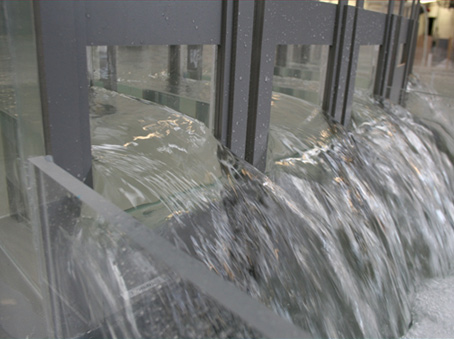
Al Khumra Delivery Basin
Client: ABULIJADAYEL CO. CONTRACTING & MAINTENANCEScale: 1/10th
The Pumping Shaft included three sumps with each sump containing eight submersible KSB pump units. The pumps in each sump operated on a seven duty one standby basis with the sumps operating on a duty / duty / standby basis. The maximum achievable pumped outflow from two duty sumps would be 14.5 m3/s.
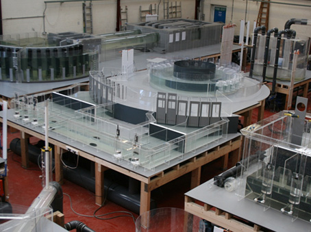
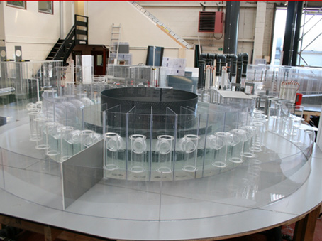
The Upper Delivery Basin was to maintain the required discharge of flow to each of the AK treatment streams. The Upper Delivery Basin was constructed above the Pumping Station, each pump discharged flow into a peripheral channel which in turn fed the distribution bay. Flow was drawn from the discharge bay via six sets of outlet weirs, one of which is a bypass pipe. The sump and pump duties will be rotated between sumps A, B and C.
Irrespective of the pump duties the requirement was to distribute the flow in the required proportions between treatment streams AK1, AK2, AK3 and AK4. In phase two AK1 will be deactivated but AK5 will be brought online.
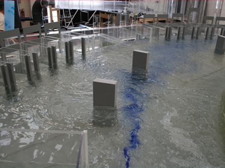
A required flow discharge rate over each of the weirs for both the 10.5 m3/s Initial MLS and 14.5 m3/s Future MLS Arrangements was defined by the Client based on the treatment capacity of each plant. To ensure that the AK Waste Water Treatment Plants (WWTP) are not overloaded it was critical that under the 10.5 m3/s Initial MLS and 14.5 m3/s Future MLS Arrangements flow was distributed as close as possible in the required proportions between the outlet streams to avoid overloading of the treatment process. An acceptance criteria of +/- 5% of the required value was adopted as the acceptable deviation away from the design flow. Under low flow conditions it was agreed that a greater deviation away from the design flow could be tolerated as there is spare capacity in the WWTP’s under these conditions.
During the 10.5 m3/s Initial MLS Arrangement the requirement was to distribute the flow in the required proportions between treatment streams AK1, AK2, AK3 and AK4. In the 14.5 m3/s Future MLS Arrangement AK1 will be deactivated but AK5 will be brought online.
The purpose of the model study was to establish the operating characteristics of the system and to develop the design, where considered necessary, to achieve a satisfactory hydraulic environment over the full range of anticipated flows.
The objective of the design is to ensure that the outlet weir configuration allows acceptable flow distribution for both 10.5 m3/s Initial MLS and 14.5 m3/s Future MLS Arrangements. The 10.5 m3/s Initial MLS Arrangement (before commissioning of AK5), is as follows:
|
10.5 m3/s Initial MLS Arrangement |
||
|
Hydraulic Structure |
Required Flow |
Percent of Flow |
|
AK1 |
1.00 m3/s |
9.5% |
|
AK2 |
1.50 m3/s |
14% |
|
AK3 |
3.00 m3/s |
28.5% |
|
AK4 |
5.00 m3/s |
48% |
|
Total |
10.5 m3/s |
|
For the 14.5 m3/s Future MLS Arrangement, (commissioning of AK5 and decommission of AK1), is as follows:
|
14.5 m3/s Future MLS Arrangement |
||
|
Hydraulic Structure |
Required Flow |
Percent of Flow |
|
AK2 |
1.50 m3/s |
10% |
|
AK3 |
3.00 m3/s |
21% |
|
AK4 |
5.00 m3/s |
34.5% |
|
AK5 |
5.00 m3/s |
34.5% |
|
Total |
14.5 m3/s |
|


