Leeming Reservoir
Client: Yorkshire Water LimitedScale: 1/20th
Leeming Reservoir is located approximately one kilometre south east of the village of Oxenhope. The reservoir is impounded behind an earthfill embankment and the spillway discharges into Bridgehouse Beck which feeds into the River Worth just upstream of Keighley.
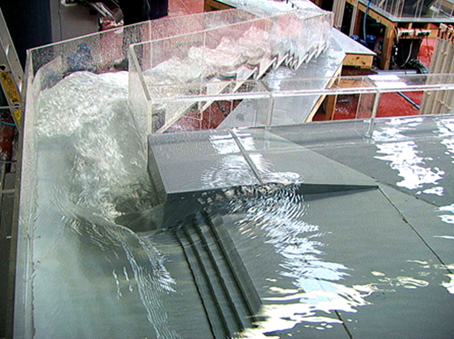
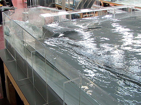
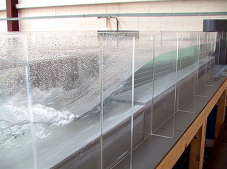
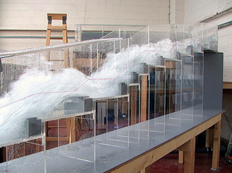
The overflow system consists of a 36.6 m long sideweir overflow which discharges into a tumble bay arranged normal to the embankment. A semi-circular bywash channel discharges into the upstream end of the tumble bay. The spillway consists of a stepped cascade approximately 5.2 m wide and some 120 m long which falls some 24 m before terminating at the receiving watercourse. A compensation water channel joins the main spillway at its lower end but this element was not considered in the model test.
The purpose of the tests was to determine the precise characteristics of the overflow arrangement and, if necessary, develop modifications to ensure that the works can safely pass the specified FEH/FSR PMF flows.
Further to initial calibration and demonstration of the model the objectives of the study were refined to include the following:-
- To limit the design flood rise in the reservoir (excluding the wave surcharge allowance) to 1.00 m above the weir crest at the FEH PMF flow for Case 1 and Case 2.
- To contain the maximum outflow of 80.1 m3/s from the spillway tumblebay within the existing sidewalls of the stepped spillway cascade channel.
- To provide adequate energy dissipation at the lower (downstream) end of the stepped spillway cascade channel to ensure no downstream scour damage for flood flows arising from storms of 100 and 200 year return periods, and to check the possible effects on the downstream toe of the dam for a flow of 80.1 m3/s.
A number of preliminary options were identified for investigation to increase the capacity of the overflow to achieve not greater than 1.00 m reservoir rise at the FEH-PMF flow included the following:-
- Re-profiling the right and left hand overflow wing walls.
- Increasing the weir length.
- Modifying the overflow weir to an Ogee profile.
- Deepening the tumble bay and the head of the spillway channel by a depth of up to 2.5 m.
It was considered that these preliminary options may be subject to change and refinement following initial calibration and demonstration of the model. The options were subsequently revised to include the following:-
- Re-profiling to the right (downstream) weir abutment wall.
- Deepening the tumble bay and the head of the spillway channel by a depth of up to 2.5 m.
- Widening the tumble bay and the head of the spillway channel by a depth of up to 3.0 m.
- A combination of deepening and widening the head of the spillway channel by a depth of up to 2.5 m and width of up to 3.0 m.
- Investigation of measures to reduce turbulence and contain flow within the existing sidewalls of the stepped spillway cascade channel. Initially to comprise infilling and re-profiling of the steps.
- Investigation of measures to provide increased energy dissipation at the foot of the cascade for flows up to the 1/200 year storm return period. Initially to comprise a slotted weir located within the spillway cascade channel immediately at the confluence with the compensation water channel.


